Over the last 20 years ventricular tachycardia (VT) ablation has evolved from a treatment modality for selected patients withrecurrent haemodynamically tolerated VT (which can be mapped during ongoing arrhythmia), to a therapeutic option for patients with tolerated and untolerated VT using substrate-based ablation strategies.1 The substrate for VT after myocardial infarction (MI) consists of areas of myocardial fibrosis interspersed with viable myocytes creating slow conduction through the scar.2 The latter is an important precondition for reentry; the most common underlying mechanism of scar-related VT. Inhomogeneous scars also occur in other diseases such as non-ischaemic cardiomyopathy (NICM), sarcoidosis and repaired congenital heart disease.3-5 Substrate-based VT ablation procedures currently depend on extensive electroanatomical mapping (EAM) to delineate bipolar1,6 and unipolar7,8 low voltage areas, and to identify abnormal electrograms such as fragmented electrograms and late potentials.4,9-11 The limitations of EAM (time-consuming, inaccurate delineation of intramural scars, attenuation of electrograms by epicardial fat) on the one hand, and the availability of different imaging modalities (providing detailed anatomical information,12-15 characterising myocardial scars,12,16-22 delineating epicardial fat15,23) as well as the progress in imaging acquisition and processing on the other hand, have stimulated clinical electrophysiologists to study image integration during VT ablation procedures. Various imaging modalities such as multidetector computed tomography (MDCT), contrast-enhanced magnetic resonance imaging (CE-MRI), intracardiac echocardiography (ICE) and nuclear imaging modalities have been applied; however, most available data are derived from MDCT and CE-MRI studies conducted in the post-MI patients - MDCT because of the higher spatial resolution if compared with CE-MRI and nuclear imaging modalities, and CE-MRI as current gold standard to visualise fibrosis. Image integration has been used to identify and delineate the substrate for VT during the procedure,12,16-22 to avoidablation in the vicinity of coronary arteries,15,23 to delineate epicardial fat tissue15,21 and to assess ablation lesions.24,25 In this review, reported applications and the potential advantages and limitations of the different imaging modalities are discussed.
Image Registration
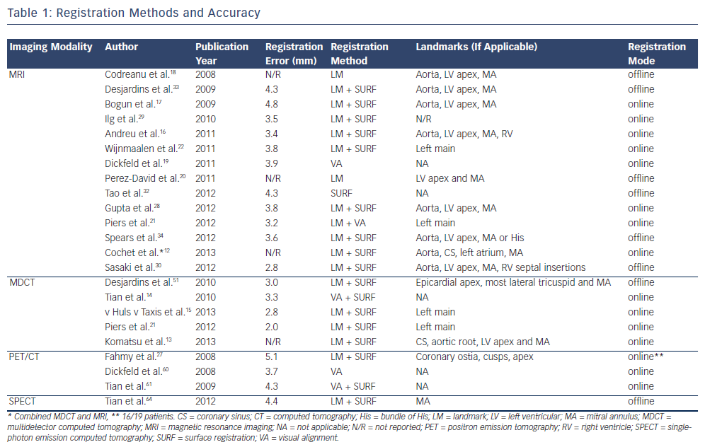
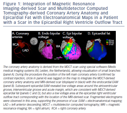
An important prerequisite for the use of image integration to guide mapping and ablation is the accurate registration of EAM and imaging data. Of note, image registration has mainly been performed during stable sinus or paced rhythm, and may be less reliable during VT activation mapping due to potential differences in cardiac morphology. An overview of studies on integration of imaging data with ventricular EAM and the reported registration accuracy is provided in Table 1. It is important to realise that a small registration error (the distance from an imaging surface to the EAM surface) does not necessarily imply good registration accuracy. Automated surface registrationtools, which are provided by commercially available three-dimensional (3D) mapping systems,13,15,22,25-30 typically minimise this distance by translation movements and circumferential and axial rotation. These registration algorithms may result in significant rotation errors, especially if only the symmetrically shaped left ventricle (LV) is mapped and low resolution imaging modalities are used.31 Indeed the registration accuracy of MRI images with LV EAM has been evaluated using different registration models, and it could be demonstrated that the best correlation between bipolar voltage and scar transmurality could be achieved by avoiding any circumferential or axial rotationduring the registration process.32 Mapping of well defined anatomical structures such as the ostium of the left main artery or additional chambers can improve the registration accuracy. In a phantom model, incorporation of EAM of the aorta in the registration process resulted in substantial improvement, as assessed visually and by the EAM-to-MRI surface distance of both LV and aorta.31 Several clinical studies have used the aorta and the ostia of the coronary arteries, which can confirm correct position by contrast injection if an open irrigated-tip catheter is used (see Figure 1, panel A),15,21,22 or a coronary sinus catheter12,13 to improve registration accuracy or to monitor the registration stability throughout the procedure.
Lessons Learned from Integration of Preacquired Magnetic Resonance Imaging Images
The feasibility of MRI integration during EAM of the LV was first demonstrated by Reddy et al. in phantom and animal models in 2004.31 To evaluate the registration accuracy, iron oxide injections were performed in five pigs before MRI acquisition. Their position was marked on the integrated MRI image and subsequently targeted for radiofrequency (RF) catheter ablation. At gross pathology the ablation lesions were localised close (mean distance 1.8 ± 0.5 millimetres [mm]) to the iron oxide targets, suggesting that MRI integration mayallow imaging-guided ablation of MRI-derived target sites.
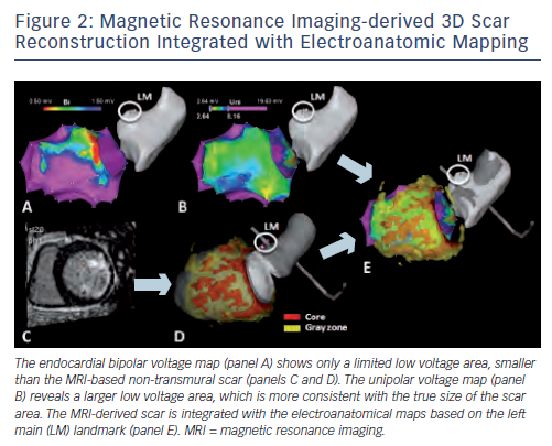
In humans, offline comparison of EAM data and CE-MRI-derived scar data could demonstrate a good overall correlation between the MRI-reconstructed post-MI scar surface and low bipolar voltage areas. However, CE-MRI allowed even improved identification of scar areas not sufficiently delineated by EAM, thereby paving the way for true MRI guidance during the VT ablation procedure.18,33 The first study on realtime integration of MRI-derived scar distribution during VT ablation could demonstrate that the integrated scar information facilitated substrate mapping and could be used as a guide to VT isthmus sites in 15 post-MI patients.22 These findings were confirmed in a second series of 13 patients with frequent premature ventricular complexes (PVCs) and 10 patients with VT after MI.28 It should be noted that although scars due to MI are predominantly localised subendocardially, non-transmural parts of the scar, in particular, remain undetected by bipolar voltage mapping (see Figure 2).22 These parts of the scar may, however, contain critical parts of the VT reentry circuits, and can be visualised duringrealtime integration of the CE-MRI-derived scar information; supporting the important complementary information provided by MRI.22
The limitation of electroanatomical voltage mapping to fully delineate the 3D geometry of scar has also been reported in patients with NICM, in whom scars are typically localised intramurally orsubepicardially.17,21,34 Intra-procedural registration of MRI-derived scars in patients with NICM has demonstrated that critical components of ventricular arrhythmias are confined to scar tissue;17 and it has been reported that MRI integration in patients presenting with VT can reveal scars not identified by EAM, which may have important diagnostic and therapeutic consequences.25 In a small series of NICM patients, the distribution of contrast enhancement, which was classified as endocardial, intramural or epicardial, corresponded with the location (endocardium or epicardium) containing critical components of the VT circuit. This finding suggests an important role for MRI in choosing the appropriate procedural strategy, which can be either endocardial, epicardial or both.17 Notably, half of the patients had predominantly endocardial scar in this study,17 which is reported to be less common in patients with NICM.35 Further studies are required before MRI-derived scar distribution can be used to guide preprocedural planning.
Not only the presence of enhanced regions, but also MRI-derived scar characteristics have been correlated with VT-related sites and local electrophysiological findings in patients with prior MI and NICM. Isolated potentials and critical sites of reentrant VT (based on pace and entrainment mapping) were associated with high infarct scar transmurality.30 In another study, also conducted in post-MI patients, 71 % of VT isthmus sites were localised within the infarct core (defined as signal intensity [SI] >3 standard deviations above remote myocardium), while the remaining isthmus sites were localised in transmural border zone with SI slightly lower than this cut-off.33 Electrogram characteristics consistent with slow conduction such as prolonged duration, late potentials and fractionated electrograms were also related to higher scar transmurality in patients with NICM.21 The association between MRI-derived scar characteristics and EAM-based electrophysiological parameters has recently been used to create non-invasive 3D substrate maps in post-MI patients. These MRI-derived substrate maps showed a remarkably high resemblance to the endocardial electroanatomical substrate maps.30
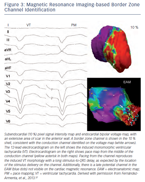
Similar to the method that adapts bipolar voltage thresholds of EAM to display channels of relatively higher voltages within low voltage regions,36 some investigators have attempted to identify relatively low SI channels within higher SI post-MI scars on MRI.16,20,37 Using variable SI and voltage thresholds, a good correlation regarding the location (segments) and orientation (perpendicular or parallel to the mitral annulus) of relatively low SI channels and relatively high voltage channels has been reported.20 In a recent paper, a favourable association between lower SI channels within high SI regions based on 'pixel SI scanning' (i.e. modifying the thresholds to 60 ± 5 % and 40 ± 5 %37) and channels of slow conduction identified by high density endocardial activation mapping during sinus rhythm has been reported (see Figure 3). Of importance, 17 of these 45 identified SI channels were related to VT based on pace mapping and entrainment mapping, and on localisation within the same American Heart Association (AHA) segment with the same orientation (parallel or perpendicular to the mitral annulus or intermediate).37 The validation of 3D lower SI channels within high density scars is limited by the lack of a gold standard, which would be histological 3D scar reconstruction. Application of different scar identification methods and cut-off values impede the comparison of reported data. Considering the known limited field of view of bipolar mapping,38 simply correlating the 3D CE-MRI-derived SI channels with two-dimensional (2D) bipolar voltage channels or with progressively delayed low voltage electrogram channels cannot overcome these limitations.7 In addition, advanced imaging techniques providing relatively high spatial resolution CE-MRI (1.4 x 1.4 x 1.4 mm in a recent paper37) are still unlikely to delineate channels at a microscopic level,2 which produce very low amplitude late potentials during sinus rhythm4 and diastolic potentials during VT.39 Despite all current limitations, the integration of high resolution CE-MRI-derived 3D scar characteristics with EAM is exciting. Additional studies are, however, required to determine the intra-observer and inter-observer variability of the channel identification process, both on MRI images and on EAM (including different applied scar detection methods and cut-off values for SI). Ideally, the identified channels should be compared to histology, and the clinical relevance of the channels needs to be determined by assessing the impact of ablation of CE-MRI-derived channels on procedural outcome.
Compared with other imaging modalities, the advantages of MRI integration include a higher resolution for detection and localisation of non-transmural scar areas, and the possibility of tissue characterisation (T1-weighted sequences after gadolinium administration to assess for extracellular matrix, T2-weighted sequences to assess for myocardial oedema). However, currently, MRI integration requires extensive and time-consuming (±1 hour) image pre-processing by specialists experienced in CE-MRI, which restrict its wide applicability. The most important limitation of MRI is its use in device recipients, as the majority of patients undergoing VT ablation have an implantable cardioverter defibrillator (ICD). Although ICDs may not necessarily preclude MRI if appropriate safety measures are taken, detailed evaluation of important parts of the LV (in particular the anterior segments) is hampered by artefacts due to the pulse generator.19,30 However, also based on the results of two recently published randomised controlled trials conducted in post-MI patients,40,41 early VT ablation may be considered in an increasing number of patients before ICD implantation, suggesting that CE-MRI integration may play an increasing role in the future.
Contrast-enhanced Magnetic Resonance Imaging as a Gold Standard
Although considered a gold standard, the technique of CE-MRI to delineate 3D scar geometry still has limitations. Firstly, contrast enhancement is not specific for fibrosis; T2-weighted sequences should therefore also be performed to assess for myocardial oedema.42 Secondly, the delineation of scars and in particular border zones is hampered by the partial volume effect (i.e. the averaging that occurs between high and low SI regions), which may cause overestimation of the scar size.43 Thirdly, current scar identification methods vary between studies (e.g. full-width half-maximum method, standard deviation of remote region-based methods) and although scar characteristics predict ventricular tachyarrhythmias in patients after MI independent of the scar identification method used, the size of the border zone varies by a factor of five depending on the method.44 Finally, the present scar identification methods are based on the SI of scar and/or remote myocardium in a look-locker sequence, which depend on the amount of diffuse fibrosis in remote myocardium, and on the maximum density of fibrosis in the scar area, the heart rate, contrast dose, glomerular filtration rate, haematocrit and other variables;45 scars are therefore not directly comparable between patients. Novel techniques are required to allow more accurate and objective characterisation of scars. A general disadvantage of integrating pre-acquired imaging data during VT ablation is the potential change that may occur between scan and procedure (e.g. volume, orientation of the heart) - a logical next step would therefore be on-site MRI.
On-site Magnetic Resonance Imaging Guidance
On-site MRI may provide an all-in-one solution during VT ablation,allowing catheter tracking without fluoroscopy; anatomical guidance; substrate delineation (including intramural and subepicardial scars);MRI-based identification of ablation target sites; and evaluation of ablation lesions. In 2008 the feasibility of realtime MRI-based catheter tracking to perform an electrophysiology study was first demonstrated in 10 mongrel dogs and two humans.46 In another study in pigs, a realtime MRI-tracked mapping catheter could be visualised on pre-acquired magnetic resonance angiography (MRA) and CE-MRI images. Realtime MRI-based tracking could be used to construct an EAM of the LV, which matched well with the pathological specimen.47 Although in both studies RF filters were applied to remove MRI-induced artefacts,significant artefacts remained interfering with both the surfaceelectrocardiogram (ECG) and the intracardiac electrograms, which is an important current limitation. Although the use of CE-MRI has been reported to allow evaluation of ablation lesions hours-to-months after RF energy application;24,29 no study has yet analysed the value of MRI to characterise and assess acute lesion formation during VT ablation. The required continuous gadolinium contrast infusion is only one of the problems that need to be solved. However, despite these hurdles, direct evaluation of lesion formation would be desirable to assess completeness of linear lesion but also to monitor substrate-based ablation targeting intramural scar or scar covered by epicardial fat.
Integration of Pre-acquired Multidetector Computed Tomography Images
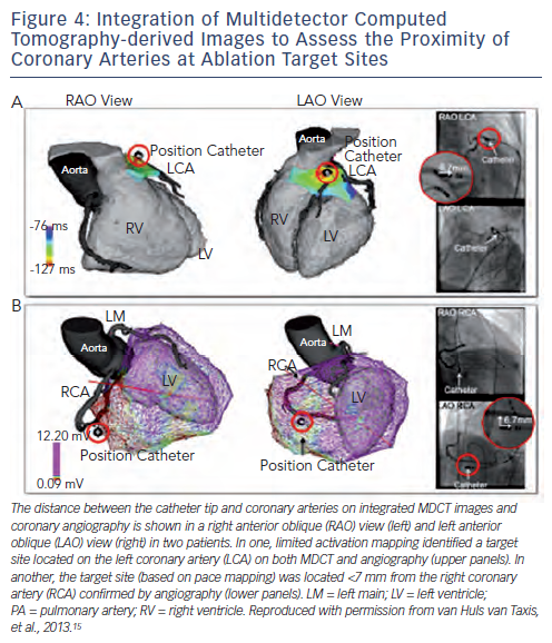
The high resolution of current MDCT images allows the detailed anatomic reconstruction of the heart, including the cardiac chambers, aortic sinus cusps, coronary vessels, epicardial fat thickness and the atrial appendages.15 The feasibility of MDCT-guided catheter manipulation was first reported in a porcine model in 2003,48 and the accuracy of MDCT-guided RF applications was demonstrated in nine mongrel dogs with a 2.1 ± 1.1 mm position accuracy of RF lesions with respect to the targeted MDCT markers.26 In humans, integration of the anatomic reconstruction of the coronary artery anatomy has been used to avoid RF energy applications at, or in close proximity to, coronary arteries, thereby potentially preventing complications of epicardial ablation (see Figure 4). The registration accuracy was confirmed by coronary angiograms in various angulations in a case report23 and in a study in 28 patients.15 The high accuracy, which can be evaluated by a single coronary injection is important as coronary angiography in some (in particular caudal) angulations can be precluded by the location pad of the EAM system, hampering accurate estimation of the distance to coronary arteries by angiography. The integration of MDCT images can also facilitate catheter ablation in patients with complex anatomy due to congenital heart disease.49
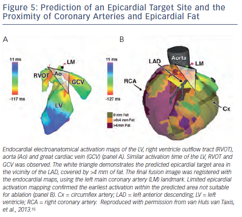
Apart from the coronary arteries, an important limitation for epicardial mapping and ablation is the presence of epicardial fat.15,50,51 Epicardial fat can be delineated by MDCT with high spatial resolution, and has been shown to cover significant parts of the ventricles, with on average 25 % of surface being covered with >4 mm fat in patients undergoing epicardial PVC or VT ablation.15 In particular, the acute margin, anterior right ventricular (RV) free wall, interventricular groove and atrioventricular groove may be covered by significant fat layers (see Figure 1).15,52 Importantly, not only scar but also epicardial fat attenuates bipolar electrogram amplitudes, thereby limiting the accuracy of epicardial substrate mapping.15,21,51 In addition, epicardial RF energy applications may be ineffective in the presence of >7 mm fat.15,51 The integration of MDCT-derived fat thickness can therefore be very helpful to classify low voltage areas (due to fat or true scar in the absence of fat, see Figure 1) and to predict and explain ineffective RF energy applications during epicardial VT ablation.
In patients with epicardial idiopathic ventricular arrhythmias the approximate site of origin can often be estimated based onelectroanatomical activation mapping of the endocardial RV, LV, aortic cusps and coronary sinus, if appropriate. The integration of MDCT images with EAM data may predict epicardial ablation failure in selected patients, which can be due to the close proximity of coronary arteries and/or a thick epicardial fat layer at the predicted epicardial site of origin (see Figure 5); thereby potentially preventing unnecessary pericardial puncture and its associated risks.15
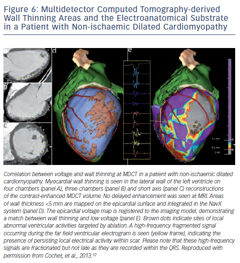
Detailed contrast-enhanced MDCT scans can provide important anatomic (wall thickness, see Figure 6), dynamic (wall thickening) and perfusion (hypoenhancement) information, which may guide to MI areas during VT ablation.14 However, in a small series of 13 post-MI patients, 87 % of abnormal electrograms, but only 46 % of ermination sites were localised within 5 mm of MDCT-derived wall thinning areas; perhaps suggesting a limited value of MDCT-derived wall thinning for identification of the VT substrate.13 Data on the use of MDCT for detection of the arrhythmogenic substrate in patients with NICM are remarkably sparse, with only three patients being included in one study.12
Compared with other imaging modalities, the main advantage of MDCT integration during VT ablation is its superior spatial resolution. Furthermore, MDCT can be performed without precautions in patients with implantable devices, and with only minor lead artefacts. Pre-processing of MDCT images is relatively easy when segmentation is performed on the CARTO® system (± 15-30 minutes), but may be time-consuming if advanced coronary artery and epicardial fat images are required (± 2 hours). As a main limitation, contrast-enhanced MDCT is associated with significant radiation exposure (currently ± 2-12 millisieverts [mSv] depending on acquisitions).14,53
Intracardiac Echocardiography
Intracardiac echocardiography (ICE) provides realtime anatomical information and allows monitoring of catheter-tissue contact,lesion formation and potential complications without radiation exposure.54-58 The anatomical information provided by ICE has been shown to be useful to guide catheter ablation of the papillary muscles,54,55 or to avoid RF delivery near the coronary artery ostia and on the aortic leaflets, as has been demonstrated in one series of five patients.58
An experimental study in seven pigs after left anterior descending infarction demonstrated a close correlation between ICE-derived infarct size and low voltage (≤2 millivolts [mV]) areas.59 In one study, Akinetic and thinned areas on ICE corresponded with the electroanatomic scar during VT ablation in 18 humans (15/18 post-MI).54 In a series of 18 patients with NICM and abnormal echogenicity on ICE imaging it could be demonstrated that the areas of increased echogenicity in the lateral wall corresponded with the endocardial and/or epicardial electroanatomical substrate.56 In these studies ICE images were visually interpreted and data on inter-observer and intra-observer variability are not available. Whether ICE-derived reconstruction of scar areas in post-MI patients and patients with NICM provides complementary substrate information to EAM data requires further investigation. Important limitations of ICE include the two-dimensional nature of ICE images, the considerable costs and the time required to acquire and interpret ICE images.
Nuclear Image Guidance
Nuclear imaging has the advantage of not being limited by the presence of implantable devices. Three studies have analysed the value of hybrid positron emission tomography (PET)/computed tomography (CT) imaging, combining low-resolution metabolic activity information from PET scans with high-resolution anatomic information from MDCT scans.27,60,61 Although areas with low metabolic activity corresponded well with low voltage areas, the net benefit of PET integration during VT ablation may be limited due to the inferior resolution of PET (currently 4-7 mm62), significant radiation exposure, high costs and the time required to create mapping system-compatible images from the PET data.63 Notably, the value of PET for identification of intramural and subepicardial scars, which are common in NICM, remains unclear as only two of the 41 patients in these studies had NICM.27,60,61 PET scanning is limited by the high costs of cyclotrons, which are required to produce radionuclides. Single-photon emission computed tomography (SPECT) images are more widely available but have an even lower resolution (±12 mm).64 SPECT-derived scar images were integrated with EAM in a small series of 10 patients, demonstrating that all successful ablation sites were located within 1 centimetre (cm) of the SPECT-derived scar area.64 Similar to PET, the added value of SPECT integration to EAM during VT ablation may be limited due to its poor resolution.
Bimodality or Multimodality Image Integration
Different imaging modalities can provide complementary information, which may be important during complex ablation procedures as has been illustrated in several case reports.49,65 In a study conducted in 10 patients with NICM, MDCT-derived fat images and MRI-derived scar images were integrated with the epicardial EAM during VT ablation and provided important insights in the complex interplay between scar, viable myocardium and epicardial fat. It could be demonstrated that in the presence of >2.8 mm fat neither bipolar nor unipolar voltage mapping can distinguish scar from fat. Specific electrogram morphologies were not affected by fat, but identified only 25 % of all scar sites.21 In a second series, MDCT and MRI-derived images were fused and integrated during VT ablation procedures in nine patients with various underlying diseases to provide detailed anatomical information (e.g. coronary artery anatomy during epicardial VT ablation) and to guide to the arrhythmogenic substrate (using MRI-derived scar areas and MDCT-derived wall thinning areas).12 These data illustrate the potential clinical applications of advanced bimodality image integration.12,21
Future Perspectives
Currently, integration of MDCT, MRI and nuclear images requires pre-processing of imaging data, which is time-consuming (typically 1-2 hours based on one study12 and our own experience15,21,22) and requires experienced observers and special software. Development of advanced software to allow more efficient or even automated analysis of imaging data would therefore be of interest, and would also make advanced image integration techniques available to electrophysiologists who do not have supporting imaging specialists.
Integration of MRI-derived images has been shown to accurately delineate ventricular scar without time-consuming EAM. Realtime image integration would be even more valuable if more specific scar features that are related to VT could be identified and displayed. In the future, MRI-based identification of critical reentry circuit sites may then allow MRI-guided delivery of RF energy applications and thereby true imaging-guided VT ablation, which has already been demonstrated feasible and accurate in an animal model.31
Although image integration has provided important insights into the substrate for VT, to date it has not been demonstrated that theintegration of MDCT, MRI or nuclear imaging data is cost-effective, improves preprocedural planning, total radiation exposure (including both imaging-related radiation and intraprocedural fluoroscopy), EAM time and, most importantly, the outcome of VT ablation. Prospective randomised studies comparing imaging-guided VT ablation to VT ablation in the setting of different diseases are required to determine whether the promising technology translates into improved acute and long-term outcome.


