


Conduction system pacing (CSP) is gaining widespread adoption as an alternative to right ventricular (RV) pacing and – in some instances – as an alternative to biventricular pacing for CRT.1 Whereas tools are evolving to facilitate implantation, there are currently no generators specifically designed to facilitate programming of CSP. Proper device programming is essential to ensure patient safety and obtain the greatest benefit from pacing therapy. Programming of His bundle pacing (HBP) has its challenges, which have been previously covered in depth.2 This review aims to provide an update on HBP programming and to outline the specificities of left bundle branch area pacing (LBBAP).
General Considerations
Device Labelling
As current implantable pulse generators are not specifically designed for CSP, it is important to indicate in the implanted device and on the patient’s device card that a CSP lead – either HBP or LBBAP – is present and which port it is connected to. This is particularly relevant when the lead is connected to the atrial port of the generator. This configuration may be confusing, as it may be mistakenly assumed during device interrogation that the atrial lead has dislodged into the ventricle.
Importance of the 12-lead ECG
When performing threshold tests, a 12-lead ECG is of utmost importance to recognise the various types of capture (selective versus non-selective conduction system capture, myocardial capture only or anodal capture). ECG analysis of HBP has been previously covered.3
Recently, criteria have been proposed to differentiate between HBP morphologies and RV septal capture by careful analysis of the near-field and far-field device electrogram).4 This could be time-sparing in the busy device clinic, but does not, as yet, replace the 12-lead ECG. Several ECG belts are commercially available that may streamline 12-lead ECG recordings.
Follow-up Frequency
In general, follow-up of HBP is performed directly after implantation, after 1, 3 and 6 months, then continued on a 6-monthly basis. This may be more frequent than with standard pacing (usually seen yearly) due to loss of HBP in up to 17% of patients and necessity for lead revision in up to 11% of patients.5
Long-term results regarding lead revision for LBBAP remain to be published, but recent mid-term data show stable and high sensed R wave amplitudes and low capture thresholds.6 Pending more data on lead stability and long-term lead performance, patients implanted with an LBBAP lead are still followed-up on a 6-monthly basis at our institution, but this may change to a yearly basis in the future.
Device Configuration
The port of the generator to which the CSP lead is connected to depends upon the baseline rhythm (sinus rhythm versus chronic atrial arrhythmia), presence of a ventricular backup lead, and indication for pacing therapy (anti-bradycardia pacing versus CRT).
Single-chamber devices are used with CSP in case of chronic atrial arrhythmias. Dual-chamber devices may be used either in sinus rhythm with an atrial and a CSP lead or – in case of chronic atrial arrhythmia – with a CSP lead connected to the atrial port and a backup right ventricular pacing lead (used in selected cases of HBP, and seldom with LBBAP) or in case of an ICD.
Biventricular devices may be used in the setting of sinus rhythm with an atrial lead, a CSP lead connected to the left ventricular (LV) port and an RV backup pacing or ICD lead. In patients with chronic atrial arrhythmias, the CSP lead is connected to the atrial port, with RV and LV leads to provide His-optimised CRT (HOT-CRT) or left bundle branch-optimised CRT (LOT-CRT), whereby CSP is combined with the right and/or left ventricular pacing to optimise electrical synchrony.7,8
The programmed parameters will very much depend upon the device configuration and the indication for pacing therapy.
Programming Considerations
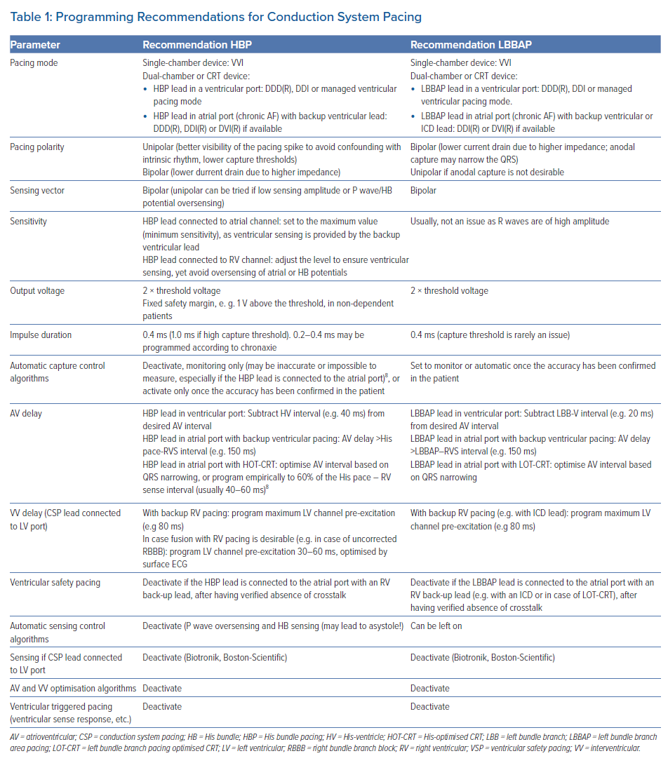
Table 1 provides an overview of programming recommendations for CSP.
Pacing Mode
CSP lead connected to a ventricular port: Patients with chronic atrial arrhythmias and a single-chamber device may be programmed to a VVI(R) mode.
Patients with dual-chamber or biventricular devices are most often programmed to the DDD(R) mode. If intrinsic conduction is present and desirable in patients in sinus rhythm, a pacing algorithm to avoid ventricular pacing (e.g. ‘managed ventricular pacing’, Medtronic) or DDI(R) mode may be programmed.
CSP lead connected to the atrial port: The DDI(R) mode may be programmed in most instances. This is particularly important in case of LBBAP due to sensing amplitudes that are often above the maximum programmable values (e.g. 4 mV) of the atrial channel. If the device is programmed in the DDD mode, a ventricular premature beat may be sensed in the atrial channel and undersensed in the ventricular channel (due to different orientations of these leads). This will trigger ventricular pacing which may be delivered during the vulnerable period. Another consideration is that devices function with ventricular-based timing when they are programmed in the DDI(R) mode. This will result in sensor-driven pacing rates that are above the programmed upper rate. For example, in a device with a programmed upper sensor-driven rate of 120 BPM (500 ms) and a paced atrioventricular interval of 180 ms, the VA interval will be 320 ms. If the AP–VS interval is 80 ms, the actual pacing rate will be 150 BPM (400 ms).2
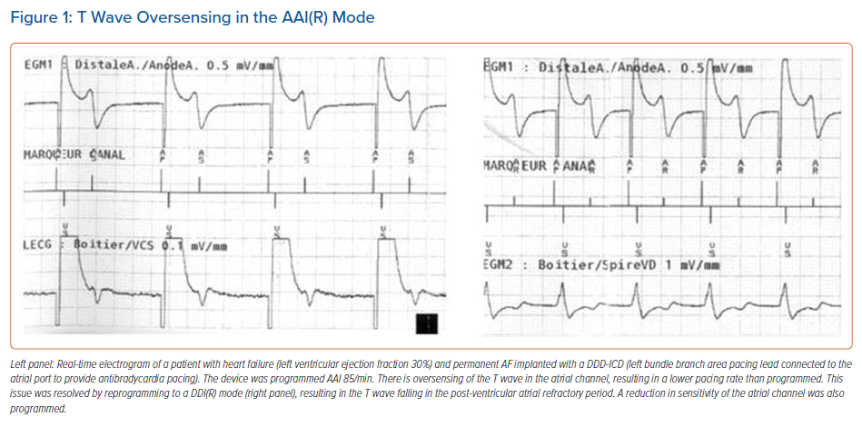
Lastly, the AAI(R) mode (e.g. in case the RV lead is only used for the ICD function) should be avoided, as there is a risk of T wave oversensing (Figure 1).
Pacing Polarity and Output
Unipolar pacing (usually not available in ICDs), other than for the left ventricular channel in some devices, results in a clear pacing spike on the surface ECG, which makes it easier to distinguish it from the intrinsic rhythm (as the QRS in HBP, and sometimes also LBBAP, may resemble that of intrinsic rhythm). Pacing thresholds are significantly lower than with bipolar stimulation, but lead impedance is about two-thirds of the bipolar lead impedance, which may negatively impact battery longevity
(as E = V2 × PW/R).9
When a CSP lead is connected to the LV-port of a CRT-device, an extended bipolar pacing configuration can be programmed (i.e. using the CSP lead tip as cathode and the RV ring or coil as anode), and can be useful in CRT-Ds, which may not have a unipolar pacing configuration of the LV channel. One should be aware that this configuration may lead to anodal capture (i.e. capture from the CSP lead tip plus the RV lead ring), which can lead to transitions in QRS morphology during threshold testing and should not be mistaken as proof of conduction system capture.9
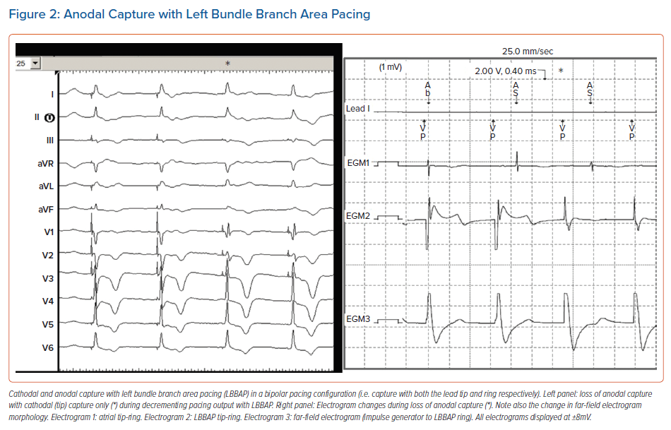
In LBBAP, anodal capture (i.e. capture with the CSP lead ring) often occurs when pacing in a bipolar configuration, as both the tip and ring of the pacing electrode penetrate into the interventricular septum. Anodal capture will attenuate the right bundle branch pattern (i.e. smaller r wave in lead V1; Figure 2). Anodal capture should be carefully observed and documented when performing threshold tests, and is generally present at higher voltages (>2.0 V/0.4 ms). Other than providing backup pacing in case of lead tip perforation, or in some instances QRS narrowing, anodal capture does not provide any proven benefit and programmed pacing output should weigh clinical need for anodal capture against excessive battery drain. In case bipolar pacing is programmed with LBBAP, it is useful to check thresholds and impedances in the unipolar configuration to check for possible perforation of the lead tip during the first follow-ups.
Strength-duration curves for His bundle (HB) capture follow a similar pattern compared to those of myocardial capture although crossing of the curves has been reported.10,11 The chronaxie (point of minimal energy drain) is significantly lower in patients with selective His bundle pacing (S-HBP). Therefore, although a pulse width of 1 ms is often employed to reduce high amplitude threshold, a narrower pulse duration (0.2–0.4 ms) may save battery life in the case of short chronaxie (E = V2xPW/R).10 In general, the pacing amplitude should be at least twice the threshold amplitude, but in selected patients (who are non-dependent, have a backup ventricular lead or in whom S-HBP is desirable), a fixed safety margin (e.g. 1 V) may also be appropriate.
It has been described that HB and myocardial thresholds can vary considerably depending upon the pacing mode (DDD or VVI) which is programmed during the threshold test.11 Until the prevalence of this finding is determined, it is wise to perform threshold tests in the device’s permanently programmed mode.
Capture management algorithms for HBP may yield erroneous values or may simply not function at all if the lead is connected to the atrial port of the device. The algorithms should be programmed ‘off’ or ‘monitor’ and only activated if clinically required (e.g. in case of a high capture threshold) and if they have been shown to provide accurate measurements in a given patient.
Of note, in Medtronic and Boston Scientific CRT devices, in case the output of an RV backup lead or ICD lead is programmed to a subthreshold value (to reduce current drain or to avoid RV capture), the LV capture management algorithm should be inactivated. This is because RV backup pacing is only delivered at the programmed amplitude during the threshold test and may result in transient asystole in case of complete atrioventricular (AV) block. Other manufacturers deliver biventricular backup pulses (Biotronik) or high-output RV backup pulses (5 V/≥0.5 ms for Abbott Cardiovascular) during LV threshold tests.
Sensing
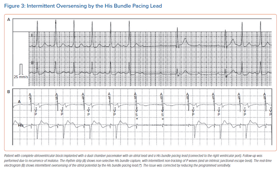
With HBP, sensing amplitudes are lower than for traditional RV pacing (generally 2–4 mV but sometimes <1 mV) and major sensing issues may be encountered when an HBP lead is connected to the atrial or RV port (sensing is not available in the LV port, except for Biotronik and Boston Scientific devices, where it may be inactivated). Ventricular undersensing may occur due to low ventricular EGM amplitude. In addition, oversensing of atrial or HB potentials can lead to asystole in the case of total AV block (Figure 3). For HBP, programming a fixed sensitivity is preferred over activating automatic sensitivity, as low amplitude signals (such as atrial and HB potentials) may lure the device into programming low values, which may result in oversensing. Sensing is generally not an issue with LBBAP, as the R wave amplitudes are higher (similar to traditional RV pacing), and there are no atrial or HB potentials.
If the CSP lead is connected to the atrial port, the RV backup pacing or ICD lead ensures ventricular sensing. In these cases, the sensitivity of the atrial channel may be programmed to the highest value (e.g. 4 mV) to reduce oversensing issues.
Atrioventricular and Interventricular Delays
When the HB lead is connected to the RV port in patients in sinus rhythm with an atrial lead, the His-ventricle (HV) interval should be accounted for and subtracted from the desired AV delay. In case of selective HBP, one can measure the spike-QRS onset delay, or simply use a default value of 40 ms. For an LBBAP lead connected to the RV port, one can program the AV delay as usual, as the delay between the left bundle branch potential and QRS onset is negligible (<20 ms). Direct LBB capture may even not be present in a substantial proportion of these patients.
In patients in chronic atrial arrhythmia with a CSP lead connected to the atrial port with a backup pacing lead or ICD lead, a paced AV delay that is sufficiently long to avoid pacing from the ventricular channel should be programmed (e.g. 150 ms). Loss of capture from the CSP lead can be deduced by the percentage of pacing from the backup lead. The interval between HBP and RV sensing is on average about 80 ms, but may be as long as 150 ms in the setting of S-HBP without correction of right bundle branch block (RBBB).9 Excessively long AV intervals (>200 ms), as well as the AAI/DDD mode or AV hysteresis should be avoided, as these may result in HBP on the preceding T wave in case of intermittent loss of HB capture.
When a CSP lead is connected to the LV port, one can either program sequential pacing or CSP-only pacing via the LV channel. The RV lead serves for ventricular sensing and for backup pacing (or delivering therapy in case of an ICD). Sequential pacing can be programmed with CSP (LV channel) pre-excitation and the VV interval set to its maximum value (e.g. 80 ms) to minimise undesired RV fusion. Pacing by the RV lead will be delivered regardless of CSP capture (i.e. even if the CSP pace–ventricular sense delay is shorter than the programmed VV interval) due to the interventricular refractory period.9 This results in pseudo-fusion, which is not harmful but results in unnecessary battery drain. Nevertheless, as in the setting of a CSP lead in the atrial port with a backup ventricular lead, this option ensures safety in the case of loss of capture by the CSP lead and makes it possible to program lower output safety margins. In order to avoid current drain resulting from unnecessary RV stimulation, pacing from the LV channel only may be programmed (with sensing from the RV lead). This should only be programmed only once stable thresholds with the CSP lead have been obtained. A potential issue might be R wave double counting if the delay between HB pace – RV sense is longer than the ventricular blanking period, e.g. in case of long HV delays or uncorrected RBBB.12 Ventricular blanking after ventricular pacing should therefore be programmed >200 ms (default in most devices), but long blanking periods after ventricular sensing should be avoided as it can result in undersensing of rapid ventricular tachycardia (VT) or VF.
In case right and/or left ventricular pacing coupled to CSP is desirable, e.g. in case of HOT-CRT or LOT-CRT, the AV delay may be optimised using QRS duration. For HOT-CRT, when programming the AV delay, empiric values of 40–60 ms or 60% of the HBP-RV sensing interval may be used.8
Programming of Specific Device Features
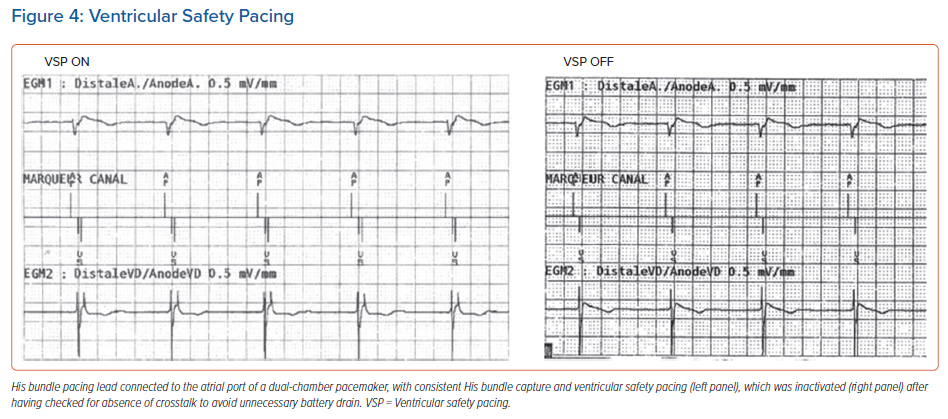
Ventricular safety pacing (VSP): This is a very useful feature in standard configurations, but can result in unnecessary pacing when a CSP lead is plugged to the atrial port. As the interval between pacing from the atrial (CSP) channel to RV sensing is very short (on average 85 ± 25 ms), the RV sensed event usually falls in the VSP window (which ranges from 64 ms in Abbott devices to 110 ms in Medtronic devices).4,9 This will result in RV pacing at the end of this window and hence pseudofusion and unnecessary battery drain (Figure 4). Before VSP is inactivated, the risk of AV crosstalk should be tested first by increasing the CSP output to its maximum value (unipolar if available) and setting the ventricular sensibility to its maximum (lowest) value, and the delay between the CSP spike and ventricular sensing analysed (and compared to during usual settings). Of note, VSP cannot be inactivated in Biotronik and Microport devices, and there is no VSP window for Boston Scientific devices.
Automatic AV and VV optimisation algorithms for CRT: Algorithms that automatically optimise AV and interventricular delays should be inactivated, as they have not been designed for CSP.
Triggered ventricular pacing algorithms for CRT: These should in general be inactivated (nominally activated in most CRT-devices) as they result in pseudofusion and unnecessary battery drain.
ICD programming: In case the CSP lead is connected to the atrial port of an ICD, all dual-chamber discrimination algorithms should be inactivated. Otherwise, RV sensing by the His lead in the case of true VT will be classified as 1:1 junctional tachycardia, and all supraventricular tachycardias will be classified as VT if the CSP lead does not sense the ventricular signals (V>A criterion). Only single-chamber discriminators (onset, stability and morphology) should be used.
Conclusion
Programming for CSP may be confusing and challenging, as no dedicated devices currently exist. Programming for HBP is generally more complex than with LBBAP because of more issues with sensing and more frequent use of ventricular backup leads. However, LBBAP leads may also be connected to the atrial or LV port of ICDs and thereby require specific programming settings. The introduction of automatic device settings for CSP is eagerly awaited. In the meantime, clinicians should recognise the possible pitfalls to ensure safe and effective CSP for their patients.
Clinical Perspective
- Effective conduction system pacing not only depends on successful device implantation but also on proper device programming. Current implantable impulse generators are not specifically designed for conduction system pacing.
- Different pacing system configurations are used depending on the underlying heart rhythm (sinus rhythm or permanent atrial arrhythmia) and the aim of pacing.
- Depending on the device configuration, different programming issues may arise.